• our science our science Our Science
    • By Industry

      • Life Sciences

      • Microelectronics

        • Semiconductor

        • Data Storage

        • Flat Panel Display

        • LED

        • Solar

      • Industrial

        • Aerospace

        • Chemical Manufacturing

        • Chromatography and Analytical

        • Coatings, Inks, and Adhesives

        • EDM

        • General Industrial

        • Glass Forming

        • Polymer Manufacturing

        • Water Treatment

    • By Role

      • Logic Manufacturers

      • Memory Manufacturers

      • Semiconductor Equipment Manufacturers

      • Chemical Suppliers

      • Bioprocessors

    • By Solution Area

      • Contamination Control

      • Fluid Management

      • Life Sciences

      • Specialty Materials

      • Substrate Handling

    • By Service

      • Analytical Services

      • Field Support Services

      • FOUP Services

      • Refurbishment Services

      • Regeneration Services

      • Technology Centers

        • China Technology Center

        • Life Sciences Technology Center

  • product catalog product catalog Product Catalog
    • Bare Die/CSP Trays

      • Tray Wizard

      • H20 Series Accessories

      • H44 Series Accessories

    • Chemistries

      • Chemical Delivery Systems

        • Solid Chemical Delivery Systems

        • Liquid Chemical Delivery Systems

      • Specialty Chemicals

        • Catalysts

        • Coating, Ink, and Adhesive Ingredients

          • Resin Monomers and Components

          • Surface Modifiers

        • Post-CMP Cleaning Solutions

          • Semiconductor Cleaning Solutions

            • PlanarClean® Cleaning Solutions

            • ESC Cleaning Solutions

          • Wide Band Gap Semiconductor Cleaning Solutions

          • HDD Media Substrate Cleaning Solutions

        • Post Etch Cleaning Solutions

          • TitanKlean® Cleaning Solutions

          • ST Cleaning Solutions

          • NOE Etchant Cleaning Solutions

        • Precursors

          • Upstream ALD/CVD Precursors

          • Advanced Deposition Materials (ADM) ALD/CVD Precursors

        • Electronic Chemicals

        • Slurries

        • Silanes

        • Organophosphorus Compounds

        • Specialty Acrylates and Methacrylates

        • Siloxanes

        • Specialty Additives

        • Ligands

        • Wafer Reclaim

    • Fluid Management Systems

      • Fittings Selection Tool

      • Liquid Packaging

        • Chemical and Bioprocessing Containers

          • FluoroPure® HDPE Blowmolded Drums

            • FluoroPure® Advantage Trilayer HDPE Blowmolded Drums

            • FluoroPure® Trilayer HDPE Blowmolded Drums

          • FluoroPure® Composite Drums

          • FluoroPure® Custom Products

        • Single-Use Assemblies

          • 2D and 3D Bags

          • Mixing Systems

          • Motion Bioreactor Bags

          • Microcarrier and Cell Separation Systems

          • Secondary Containment

        • NOWPak® Liner Based Systems

        • Sentry® Quick Connect Systems

        • FluoroPure® Intermediate Bulk Containers

        • FluoroPure® Port Options, Tools and Accessories

        • Tube Sets and Manifolds

        • Custom Dip Tubes, Tanks, and Containers

        • FluoroPure® Pressure Vessels

        • Process Tanks

      • Valves Selection Tool

      • Fluid Handling

        • Fittings

          • PrimeLock® Tube Fittings

          • PrimeLock® ESD Tube Fittings

          • PrimeLock® Accessories

          • Flaretek® Tube Fittings

          • Flaretek® Accessories

          • Cynergy® Fittings

          • Cynergy® Accessories

          • EP PFA Flare Fittings

          • EP PFA Flare Fitting Accessories

          • PureBond® Welded Tube Fittings

          • Quikgrip® Tube Fittings

          • Quikgrip® PFA Nuts

          • Integral Ferrule Tube Fittings

          • Integral Ferrule Accessories

          • Barb PFA Tube Fittings

          • Dual Containment Fittings

          • PureBond® Welded Pipe Fittings

          • PureBond® Accessories

          • NPT Pipe Fittings

          • NPT Accessories

        • Valves

          • CR and CH Series Valves

            • CR4 Series Valves

            • CR8 Series Valves

            • CH8 Series High-Temperature Valves

          • Integra® Valves

          • Cynergy® Valves

          • EP PFA Valves

          • Manifolds and Assemblies

          • Plug Valves

          • Needle/Metering Valves

          • Stopcock Valves

          • Check Valves

          • Valve Accessories

        • Fluid Handling Accessories

          • Spray Products

          • Aspirators

          • Fasteners

        • Valves Selection Tool

        • Fittings Selection Tool

        • Tubing and Pipe

        • Custom Products

      • Process Monitoring

        • Process Control

          • Integrated Flow Controllers

          • NT™ Proportional Control Valves

          • Photochemical Dispense Pumps

        • Process Measurement

          • Concentration Monitors

          • Electronic Flowmeters

          • NT™ Pressure Transducers

        • Particle Characterization

    • Gas Filtration and Purification

      • Gas Diffusers

        • Chambergard™ Gas Diffusers

      • Gas Filters

        • Other Gas Filters

        • In-Line PTFE Gas Filters

        • In-Line Stainless Steel Gas Filters

        • In-Line Nickel Gas Filters

        • Surface Mount Gas Filters

      • AMC Filters

        • Stepper and Scanner Filters

        • Process Tool Air Filters

        • Facility Filtration

        • Filter Housings and Stand-alone Filter Cabinets

      • Gas Purifiers

    • Hard Disk Component Handling

      • Storage Boxes and Individual Disk Packages

      • Read-Write Trays and Carriers

      • Disk Shippers

      • Disk Process Carriers

    • Liquid Filtration and Purification

      • Liquid Filters

      • Liquid Purifiers

      • Liquid Filter Housings

    • Mask and Reticle Handling

      • Reticle Pods and Purge Cabinets

      • Mask Carriers and Shipping Boxes

      • Mask Packages

    • Other Substrate Handling

      • Miscellaneous Device Processing

      • Solar Cell Solutions

    • Specialty Materials

      • Premium Graphite

        • Industrial Graphite Grades

        • Semiconductor Graphite Grades

        • Life Sciences Graphite Grades

        • Premium Graphite Components

        • Glass Forming Graphite Grades

        • GLASSMATE® Components

        • Graphite Processing Options

      • Coatings

        • Chucks

        • Plasma Enhanced Chemical Vapor Deposition (PECVD) Coatings

        • Caerus™ Coating Technology

        • Pegasus™ Coating Technology

      • Premium Silicon Carbide

        • SUPERSiC<sup>®</sup> Silicon Carbide Components

        • SUPERSiC<sup>®</sup> Silicon Carbide

      • Advanced Cleaning Materials

    • Specialty Gases

      • Specialty Gas Mixtures

      • Gas Delivery Cylinder Systems

      • Gas Delivery Cabinet Systems

      • Gases

    • Wafer Handling

      • Wafer Processing

        • CMP Cleaning Brushes

        • CMP Pads

        • 300 mm Front Opening Unified Pods (FOUPs)

        • 200 mm Wafer Processing

        • 200 mm Accessories

        • 150 mm Wafer Processing

        • 150 mm and Smaller Wafer Carrier Accessories

        • 125 mm Wafer Processing

        • 100 mm Wafer Processing

        • 76.2 mm 3" Wafer Processing

        • 2.5" and Smaller Wafer Processing

        • Labware

        • Chucks

      • Wafer Shipping

        • 150 mm Wafer Shippers

        • 125 mm and Smaller Wafer Shippers

        • 300 mm Wafer Shippers

        • 200 mm Wafer Shippers

      • Finished Wafer Shipping

        • SmartStack® Contactless Horizontal Wafer Shipper

        • SmartStack® Horizontal Wafer Shippers

        • Film Frame Rings and Shippers

  • resources resources Resources
    • Reference Materials

    • Technical Information

      • Calculators and Tools

      • Chemical Compatibility

      • Chemlock® Filter Housing Technical Information

      • Component Technical Information

      • Entegris Test Standards and Protocols

      • FAQ

      • Formulas

      • Glossary

      • Material Properties and Safety

      • Particle Characterization Applications

    • Industry Insights

      • 3D NAND Solutions

      • Achieving Hydrogen Purity Standards for Fuel Cells

      • Advanced Coatings

      • Advanced Deposition Materials Innovation

      • Automotive Reliability

      • Cars and Chips: The Acceleration of Electronic Systems

      • Chasing the Perfect Pattern

      • Chemical Mechanical Planarization (CMP)

      • Clean Chemical Delivery

      • Clean Gas Delivery

      • CMP Process Monitoring

      • Cold Chain Bioprocessing

      • Dual Containment Tubing

      • Electrostatic Discharge (ESD) Prevention

      • Enabling Advanced Lithography

      • End-to-End Gas Filtration Solutions

      • Food and Beverage Contamination Control

      • Front-end to Back-end Solutions

      • Glass in Front; Glass in Back

      • High-Density Cell Banking

      • High Purity Chemical Manufacturing

      • Holistic Approach to Enabling Device Performance, Yield, and Reliability

      • Internet of Things

      • Low-Temperature Bioprocessing

      • More Than Just a Chip Tray

      • Operational Excellence

      • Pandemic Response

      • Particle Characterization

      • Pervasive Defectivity in Semiconductor Manufacturing

      • Protecting Your Data Center Environment from Gas-Phase Contamination

      • The Rare Air of the Semiconductor Fab

      • Silicon Carbide CMP Solutions

      • The Silicon Precursor Toolbox for Low-Temperature Deposition

      • Solid Precursors and Delivery Systems

      • Solutions in Advanced Logic

      • Solving Advanced Technology Challenges with Innovative Materials

      • Storage Class Memory

      • Targeted Contaminant Removal

      • Specialty Gases and Delivery Systems for Ion Implantation

      • Accelerating Speed-to-Yield with High-Purity Materials Solutions

    • Ensights (Blog)

    • Scientific Report

  • about us about us About Us
    • Corporate Overview

    • Corporate Social Responsibility

    • Careers

    • Events

    • Investor Relations

    • Legal/Trademark Notices

    • Locations

    • News Releases

    • Media Coverage

    • Entegris Blog

    • Manufacturing

FluoroLine® Tubing and PureBond® Pipe Technical Information


Long-term Strength

The long-term hydrostatic strength of PFA used in FluoroLine ultrapure tubing, Cynergy® tubing and PureBond pipe has been determined in accordance with the test procedures outlined in ASTM D2837. "Obtaining Hydrostatic Design Basis for Thermoplastic Pipe Materials." This analysis has assigned a 100,000 hour long-term strength value of 1600 psig at 73°F (23°C) for FluoroLine and Cynergy tubing, and PureBond pipe.

Long-term Hydrostatic Strength of Teflon® PFA

The following is a simplified summary of how this value was determined.

  1. Specimens of 440HP PFA tubing are subjected to constant internal water pressure at different pressure levels and the time to rupture is measured. Stress on each specimen is calculated from the pressure by means of a pipe design equation.

         P(D-t)
    S=    2t

    Where:
    S = stress, psi
    P = pressure, psig
    D = average outside diameter, inches
    t = minimum wall thickness, inches

    Testing is continued for 10,000 hours (approximately 13.6 months) according to the rigid specifications in ASTM D2837. An accurate, reproducible linear plot of hoop stress vs. time to rupture on log-log coordinates is generated as shown in the chart above.

  2. The stress rupture data is analyzed by statistical regression to generate a hoop stress vs. time equation. This equation is extrapolated mathematically to 100,000 hours (approximately 11.4 years) to obtain a 100,000 hour design stress. This is the first step in determining working stress.

  3. The next step makes use of a division of the entire design stress scale into continuous increments, one of which is approximately 25% larger than the one below it. These increments in psi are 800, 1260, 1600, 2000, 2500, etc. PFA is assigned the threshold value of the increment in which its 100,000 hour design stress falls, called the hydrostatic design basis. This becomes the fundamental stress from which working stress is calculated. The findings of this evaluation have resulted in a hydrostatic design basis for FluoroLine and Cynergy tubing, and PureBond pipe of 1600 psi at 73°F (23°C).

Safety Factor

FluoroLine and Cynergy tubing and PureBond pipe product lines were developed with the end user's safety in mind. The quality assurance measures used in the manufacture of the tubing, pipe, fittings and related components assure system integrity. To compensate for the variables involved in each application, a safety (design) factor has been incorporated. This will allow for:

  • Occasional pressure surges/water hammer
  • Improper piping installation and/or support, to some extent
  • Stresses due to thermal expansion and contraction
  • Longitudinal stresses in the pipe

Based on the hydrostatic design the hydrostatic stress committee of the Plastic Pipe Institute (PPI) has recommended a minimum safety (design) factor of 200%. Entegris suggest that a safety factor of 250% may better accommodate these type of services. Therefore, the hydrostatic design stress would be:

            1600 psi
HDS =     2.5

HDS = 640 psi

The hydrostatic design stress is defined as the maximum ho9op stress in the pipe wall due to internal hydrostatic pressure that can be applied continuously with a high degree of certainty that pipe failure will not occur within a long period of time.

Flow Requirements

FluoroLine tubing and PureBond pipe each have an exceptionally smooth bore. This accounts for their excellent flow capacities. There is less drag, less turbulence at high flows, no corrosion and no wetting of the PFA. They are also resistant to bacterial growth because no nutrients or organics are present. FluoroLine tubing and PureBond pipe retain these flow characteristics over their service lives.

Initial flow estimates can be made by knowing the inside diameter of a particular tubing or pipe size and assuming a nominal flow velocity. The following illustrates this exercise.

Where:
Q = flow, gallons per minute
V = velocity, feet per second
D = inside diameter, inches

By knowing the required flow rate and assuming a nominal flow, the tubing or pipe diameter or velocity can be estimated.

From these three formulas, an approximate range is established for the tubing or pipe ID, flow rate and flow velocity.The next step is to determine if the tubing or pipe size estimated exhibits an acceptable pressure loss based on the specific flow requirements. The Hazen and Williams formula can be used to determine the frictional pressure loss, as shown.

Where:
Delta P100 = frictional pressure loss, psig/100 feet of tube or pipe
Q = flow, gallons per minute, fluid with specific gravity 1.0
C = friction factor coefficient, 155 for PFA tube or pipe
D = inside diameter, inches

The chart below shows this relationship between flow, pressure loss and velocity on the different PureBond pipe sizes. For fluids with a specific gravity other than 1.0, a rough estimate of the pressure loss due to this viscosity is approximated by multiplying the Hazen and Williams frictional pressure loss per 100 feet by the specific gravity of the fluid. Graphs showing the relationship between flow and pressure loss for FluoroLine® tubing can be found here.

In addition to the pressure loss experienced in tubing and pipe, the loss due to fittings should also be considered. The standard practice is to add the equivalent length of tubing or pipe each fitting represents, to the total footage for pressure loss calculations.

Upon completion of all calculations, including pressure loss due to fittings and valves, be sure that:

  • The system pressure drop does not exceed the pressure rating of the selected components
  • The pump pressure exceeds the system pressure drop, but does not exceed the pressure rating of the selected components.
Flow Rate vs. Friction Loss of Water for PureBond Pipe

Tubing Support

To provide trouble-free service, long lengths of PFA tubing must be supported. Supporting the tube minimizes the stress and strain within the tube wall as well as accommodates drainability. Tube support distances are dependent on the tubing size (ID and OD), the specific gravity of the fluid being transported through the tube, the average temperature of the tubing and the acceptable amount of vertical tubing deflection between supports. The formula used to determine the spacing between tube supports is shown:
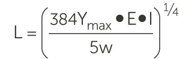
Where:
L = length between pipe supports
Y(max) = maximum allowable tube deflection between supports
E = modulus of elasticity
I = tubing moment of inertia
W = weight of tubing and fluid in the tubing

Pipe Support

  • Long lengths of PureBond pipe must be supported to provide trouble-free service. This will minimize the degree of stress and strain within the pipe wall to an acceptable level. The minimum recommended distance between pipe supports has been calculated by taking into account the weight of the pipe, its contents and an allowable stress. As shown below, the distance between supports is also affected by pipe size and temperature.

  Size                  23°C (73°F)
   1/4"                 68 cm (26.9")
   1/2"                 82 cm (32.4")
   3/4"                 91 cm (36.0")
   1"                   101 cm (39.6")
   2"                   122 cm (48.0")

100°C (212°F)
55 cm (21.5")
67 cm (26.4")
73 cm (28.8")
79 cm (31.2")
98 cm (38.4")

177°C (350°F)
37 cm (14.5")
48 cm (18.0")
49 cm (19.2")
55 cm (21.6")
64 cm (25.2")

  • The specific gravity of a fluid greater than 1.0 can adversely affect the spacing of the pipe supports. The recommended spacing distance should be multiplied by the factor indicated, resulting in shorter distances between supports.

Specific Gravity
1.00
1.25
1.50
1.75
2.00
2.25
2.50
2.75
3.00

Factor
1.00
0.94
0.89
0.86
0.82
0.79
0.76
0.74
0.72

  • The pipe supports specified should not be the type that clamp the pipe tightly and restrict movement, especially when thermal expansion and contraction are involved. Not using this type of clamp will prevent abrading and damage to the pipe wall. An excellent option to intermittent pipe supports is to continuously support the pipe by laying it in a plastic trough. A commonly extruded shape such as an angle, channel or conduit works well as a trough. In addition, it is less costly than numerous pipe brackets.
  • Vertical sections of pipe, referred to as risers, must also be supported. The top and base of the risers should always be supported. Brackets should be at 5' (1.5 m) vertical intervals.
  • Accessory items such as valves, filter housings, etc. should not be fully supported by the pipe. Individual supports should be specified for all heavy components connected to a piping system.